Wall thickness is one of the first dimensions to review in an injection-molded part because it affects both how the cavity fills and how the part cools after filling.
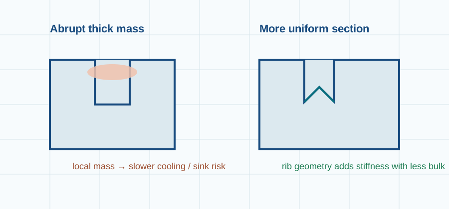
Why uniform walls matter
Injection molding is a thermal process. Thick regions hold heat longer than thin regions, so large thickness changes create uneven cooling and uneven shrinkage. That can show up as sink marks, internal stress, dimensional drift or warpage. Uniformity does not mean every surface must have exactly the same thickness, but transitions should be intentional and gradual.
A practical starting range
There is no universal wall thickness because the usable range depends on resin flow, flow length, gate position, cosmetic requirements and structural load. For many commodity thermoplastics, designers often begin in roughly the 1–3 mm region and then confirm the range against the specific resin supplier and molder. Very thin walls may require high injection pressure and specialized tooling; very thick walls increase cooling time and sink risk.
Avoid making strength with bulk
If a wall is thick only because the part needs stiffness, consider ribs, curvature, beads or section geometry before simply adding material. Bending stiffness rises strongly with section depth, so geometry can often add rigidity more efficiently than a large solid thickness.
Transition between thicknesses
Where thickness must change, avoid abrupt steps. A tapered or radiused transition reduces local stress concentration and makes the thermal transition less severe. A hidden thick intersection at a rib, boss or corner can still create a sink mark on the opposite cosmetic surface.
CAD review checklist
Use section views or wall-thickness analysis to scan the entire model. Look for local islands of material at bosses, rib intersections, screw towers and junctions. Then discuss the thinnest flow path, thickest region, gate concept and cosmetic surfaces with the toolmaker before freezing geometry.
Related learning
Pair wall-thickness review with the DIVE-LD guides on ribs, bosses, draft and injection-molding tolerances. The individual rules interact: a boss that looks acceptable in isolation may create a thick mass where it meets a nominal wall.
Injection-molding verification
Confirm resin-grade data, mold construction, texture/draft requirements, shrinkage assumptions and the selected molder's capability.